

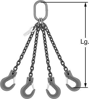
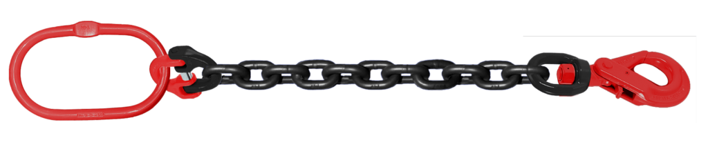
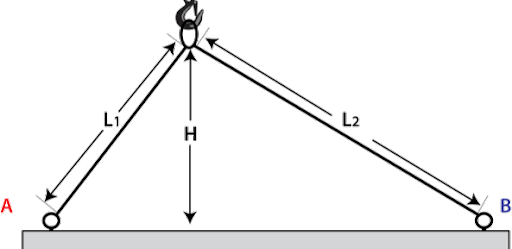
GRADE 80 CHAIN SLING CALCULATOR
*See bottom for detailed instructions on how to use the Chain Sling Calculator
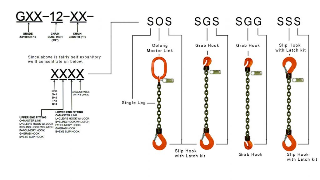
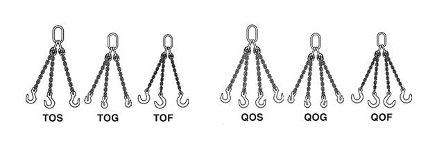
Select the style of chain sling you require
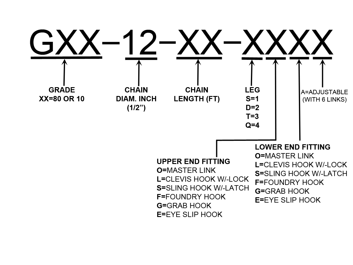
Understanding the description and how to order
1. Select the grade of chain.
2. Select the size of chain based of the load you need to lift.
3. Select the length of the legs you require.
4. Select the number of legs you need.
5. Select upper side of sling.
i.e. “S” single and then “O” Master link or “G” Grab etc…
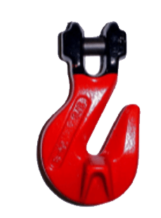
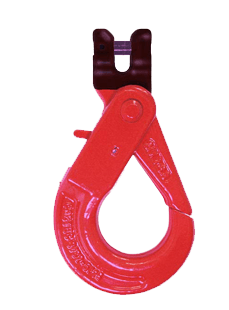
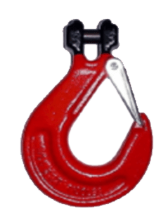
6. Select lower end fitting.
7. Select if you want to be able to adjust by adding an “A” (sometimes added at the beginning as above diagram)


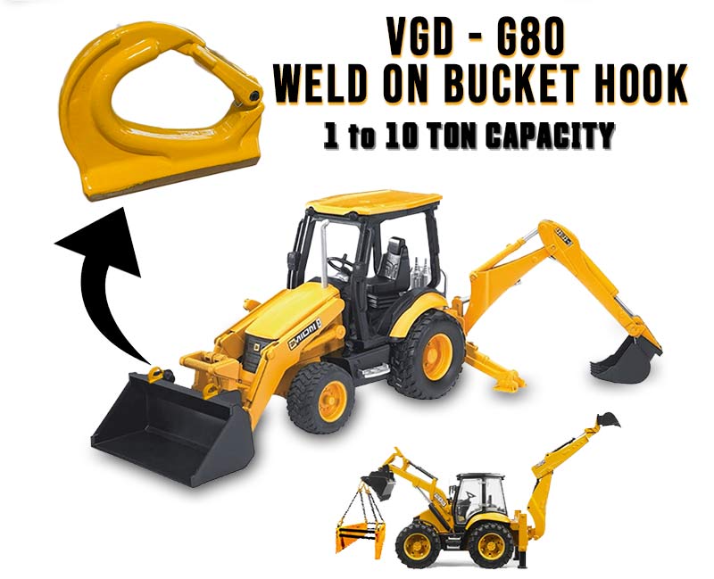
Grade 80 Weld-on hook
make your lifts safer
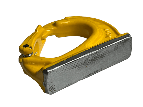
Features a large weld pad, uncoated for easy welding
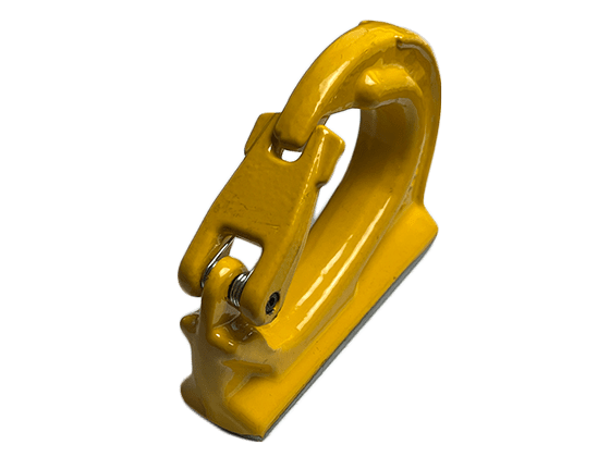
Heavy-duty integrated latch kit
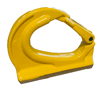
1 ton - 10 tons capacity wll
with intigrated spring loaded safety cast latch